Saturday 17 March 2018

Network Architectures for the Data Center: SDN and ACI

This chapter covers the following topics: 
■ Cloud Computing and Traditional Data Center Networks 
■ The Opposite of Software-Defined Networking 
■ Network Programmability 
■ SDN Approaches 
■ Application Centric Infrastructure 

This chapter covers the following exam objectives: 

  •  4.1 Describe network architectures for the data center 
  •  4.1.b SDN 
  •  4.1.b.1 Separation of control and data 
  •  4.1.b.2 Programmability 
  •  4.1.b.3 Basic understanding of OpenDaylight 
  •  4.1.c ACI 
  •  4.1.c.1 Describe how ACI solves the problem not addressed by SDN 
  •  4.1.c.3 Describe the role of the APIC Controller
In Chapter 10, “Network Architectures for the Data Center: Unified Fabric,” you learned about a series of technological innovations that Cisco amalgamated into a highly successful data center network architecture: Cisco Unified Fabric. Although such architecture has become a primary driver for the evolution of numerous data centers worldwide, it is essentially based on concepts and abstractions that were conceived during the 1970s and 1980s, as the Internet was being formed. 

During the last half of the 2000s, inspired by the noticeable differences between networking and other computer systems, a group of researchers began to question whether established networking practices were actually appropriate for the future of IT. Through creativity and healthy naïveté, these researchers proposed many breakthrough new approaches to disrupt well-known network designs and best practices. These new approaches have been collectively given the umbrella term Software-Defined Networking (SDN). 

As the world-leading networking manufacturer, Cisco has actively participated in developing the large majority of these cutting-edge approaches, while also creating many others. Combining innovation and intimate knowledge about customer demands, Cisco conceived a revolutionary data center network architecture called Cisco Application Centric Infrastructure (ACI). Specially designed for data centers involved in cloud computing and IT automation, ACI addresses many challenges that were overlooked by earlier SDN approaches. 

As mentioned in Chapter 10, the CLDFND exam requires knowledge about two other Cisco data center networking architectures besides Cisco Unified Fabric: Software-Defined Networking and Cisco Application Centric Infrastructure. This chapter focuses on both, exploring the dramatic paradigm shifts they have caused in data center infrastructure and cloud computing projects.

Foundation Topics

Cloud Computing and Traditional Data Center Networks

Because cloud computing is an IT service delivery model, cloud implementations become more flexible as more infrastructure elements are orchestrated to support requests from a cloud end user. And as the main system responsible for transporting data to users and between cloud resources, the data center network should be included prominently in this integration. 

However, some principles that supported the evolution of networking during the past 40 years are incompatible with the expectations surrounding cloud computing. In Chapter 10, you learned about techniques and designs created to satisfy the demands related to server virtualization escalation in data centers. For example, data center fabrics can definitely help cloud computing projects through the consolidation of Layer 2 silos that are still very common in classical three-tier topologies. And as a direct consequence, a fabric can more easily become a single pool of networking resources for a cloud software stack. Yet, the large majority of data center networks (and fabrics) are still provisioned through practically artisanal procedures. As an illustration, Figure 11-1 depicts a network configuration procedure that is probably happening somewhere as you read these words.

Image result for Data Center Network Provisioning


Figure 11-1 Data Center Network Provisioning

In the figure, a network engineer must provision the network to receive a new application consisting of virtual machines that can potentially be connected to any leaf port on this generic fabric. After some time translating the application requirements into networking terms, the professional performs the following operations:

Step 1. Creates three VLANs in every switch. 
Step 2. Adds these VLANs to every leaf access port. 
Step 3. Configures a default gateway for each VLAN at some point of this network (border leaves in the case of Figure 11-1).

Because most network engineers still use command-line interface (CLI) sessions or a device graphical user interface (GUI) to fulfill these steps , their resulting configurations are generally considered very error-prone and difficult to troubleshoot. And although some corporations maintain detailed documentation about past and current network configurations, this practice is hardly the norm for the majority of data center networks. This simple example should already reveal to you the great chasm that exists between resource provisioning for networks and resource provisioning for other technologies such as server virtualization. To make matters worse, I’m personally aware of many companies in which VLANs can be added (or removed) only during monthly maintenance windows, invariably making the network team the biggest contributor to application deployment delays. As you can easily deduce, such manual operations are highly unsuitable for cloud computing environments. For this reason alone, I completely understand why some cloud architects plan to pre-configure all 4094 available VLANs every port of a network, avoiding additional procedures during the provisioning of cloud resources. However, leveraging this design decision, these architects are disregarding important aspects such as 
  1.  Flooding and broadcast traffic may severely impact all ports, inadvertently affecting other cloud tenants. 
  2. VLANs are not the only network consumable resource. Other configurations such as access-control lists (ACLs), firewall rules, and server load balances services will still need provisioning as new tenants sign up for cloud services. 
Whereas cloud computing environments may be prepared to welcome new tenants, they should also expect that any of them may discontinue cloud services at any time. And because the network resources for a tenant are essentially defined as a set of configuration lines spread over multiple devices, decommissioning is considered an almost insurmountable obstacle in traditional networks. Consequently, even after tenants or applications are discontinued, their corresponding VLANs, routes, ACL entries, and firewall rules continue to clutter troubleshooting procedures forever. 

With the popularisation of cloud computing projects, and the increasing demand for automation and standardisation in data centers, networks began to be seriously reexamined within academic studies, service provider meetings, and boardrooms in light of the new SDN technologies.

The Opposite of Software-Defined Networking

The formal beginning of many SDN initiatives happened in 2006 with Stanford University’s Clean Slate Program , a collaborative research program intended to design the Internet as if it were being created anew while leveraging three decades of hindsight.

As clearly stated in its mission, Clean Slate did not outline a precise approach, a decision that enabled program participants to pursue extremely creative small projects and very interesting endeavors. And even after its deactivation in 2012, the project’s legacy is apparent today in the numerous network solutions being offered to support automation and cloud computing deployments in enterprise corporations and service providers. 

Unsurprisingly, presenting a conclusive definition for SDN is quite difficult. This difficulty is compounded by the SDN marketing bandwagon. With huge interest in SDN turning into hype in the early 2010s, many vendors tried to associate SDN as closely as possible with their own approach. As an example, the following list paraphrases some definitions of SDN I have compiled after a quick web search: 
  •  “SDN is an approach to computer networking where IT administrators can manage networks through the abstraction of lower-level functionalities.”  “SDN is an emerging architecture that can be translated into speed, manageability, cost reduction, and flexibility.” 
  •  “SDN enables network control to become directly programmable as the underlying infrastructure is abstracted for applications and network services.” 
  •  “SDN is the virtualization of network services in order to create a pool of data transport capacity, which can be flexibly provisioned and reutilized according to demand.” 
As you can see from this small sampling, such definitions of SDN wildly vary from precise descriptions of specific technologies to very vague statements. In my humble opinion, the effort to propose a definitive conceptualization of SDN is futile simply because these new approaches are intended to break current paradigms and, consequently, are only bounded by creativity. 

Because this chapter will explore SDN approaches that will contradict the statements made previously, allow me to introduce a definition for SDN in a different manner. 

According to John Cleese (genius from legendary comedy troupe Monty Python and neuropsychological studies enthusiast), nobody really knows how creativity actually happens, but it is pretty clear how it does not. Furthermore, as Cleese jokes in his famous lectures about creativity and the human mind, a sculptor explained his method of creating beautiful elephant statues: simply remove from the stone what is not an elephant. 

In a similar vein, allow me to propose the following question: what is the opposite of SDN for you? Please give yourself some time for reflection before reading the next paragraph. 

If you believe hardware-defined networking (HDN) is the correct answer, you are not alone. Respectfully, I do not agree with that answer, for what I think are some compelling reasons. Since the inception of the ARPANET in the late 1960s, networks have been based on devices composed of both hardware and software (network operating system), the latter of which is as carefully designed and developed as other complex applications such as enterprise resource planning (ERP). In its current model, neither hardware nor software defines how a network behaves, but rather a higher layer of control called Homo sapiens defines its behaviour. Because this “layer” is directly involved in every single change on most networks, I believe human-defined networking genuinely represents what is not SDN. (But if you still prefer hardware-defined networking, at least we can agree on the same acronym.)

As a result, SDN can be defined as the set of technologies and architectures that allow network provisioning without any dependence on human-based operations. In truth, such conclusion may explain why the large majority of SDN approaches (including OpenFlow and Cisco ACI, which will be discussed in a later section) pursue the concept of the network as a programmable resource rather than a configurable one. And as many network professionals can attest, manual configurations can easily become an operational headache as more changes are required or the network scales. 

The ways in which programming can help remove these repetitive menial tasks will be further explored in the next section.

Friday 16 March 2018

Network Architectures for the Data Center: Unified Fabric

In this Three−Tier (Three Layer) hierarchical network model, that consists of three layers: the Core layer, the Distribution layer, and the Access layer. Cisco Three-Layer network model is the preferred approach to network design.

Core Layer

Core Layer consists of biggest, fastest, and most expensive routers with the highest model numbers and Core Layer is considered as the back bone of networks. Core Layer routers are used to merge geographically separated networks. The Core Layer routers move information on the network as fast as possible. The switches operating at core layer switches packets as fast as possible.

Distribution layer:
The Distribution Layer is located between the access and core layers. The purpose of this layer is to provide boundary definition by implementing access lists and other filters. Therefore the Distribution Layer defines policy for the network. Distribution Layer include high-end layer 3 switches. Distribution Layer ensures that packets are properly routed between subnets and VLANs in your enterprise.

Access layer
Access layer includes access switches which are connected to the end devices (Computers, Printers, Servers etc). Access layer switches ensures that packets are delivered to the end devices.

Benefits of Cisco Three-Layer hierarchical model
The main benefits of Cisco Three-Layer hierarchical model is that it helps to design, deploy and maintain a scalable, trustworthy, cost effective hierarchical internetwork.

Better Performance: Cisco Three Layer Network Model allows in creating high performance networks

Better management & troubleshooting: Cisco Three Layer Network Model allows better network management and isolate causes of network trouble.

Better Filter/Policy creation and application: Cisco Three Layer Network Model allows better filter/policy creation application.

Better Scalability: Cisco Three Layer Network Model allows us to efficiently accomodate future growth.

Better Redundancy: Cisco Three Layer Network Model provides better redundancy. Multiple links across multiple devices provides better redundancy. If one switch is down, we have another alternate path to reach the destination.

Related image

Thursday 15 March 2018

File Storage Technologies

What is a file ?
file is an object on a computer that stores data, information, settings, or commands used with a computer program. In a graphical user interface (GUI) such as Microsoft Windows, files display as icons that relate to the program that opens the file.

In other terms we can say that, a file is a container in a computer system for storing information. Files used in computers are similar in features to that of paper documents used in library and office files. There are different types of files such as text files, data files, directory files, binary and graphic files, and these different types of files store different types of information. In a computer operating system, files can be stored on optical drives, hard drives or other types of storage devices.


Most modern computer systems provide security or protection measures against file corruption or damage. The data contained in the files could range from system-generated information to user-specified information. File management is done with the help of operating systems, third-party tools or done manually at times with the help of the user.
The basic operations that can be performed on a file are:
  • Creation of a new file
  • Modification of data or file attributes
  • Reading of data from the file
  • Opening the file in order to make the contents available to other programs
  • Writing data to the file
  • Closing or terminating a file operation
In order to read or modify data in a file, specific software associated with the file extension is needed.


Wednesday 14 March 2018

Block Storage Technologies

What is Data Storage ?
Data storage is a general term for archiving data in electromagnetic or other forms for use by a computer or device. ... In addition to forms of hard data storage, there are now new options for remote data storage, such as cloud computing, that can revolutionise the ways that users access data.  

Data storage describes the devices used to hold information. Storage can be considered primary storage or secondary storage, and it is measured in bytes.

Hard Disk Drive
hard disk drive (HDD), hard diskhard drive or fixed disk is a data storage device that uses magnetic storage to store and retrieve digital information using one or more rigid rapidly rotating disks (platters) coated with magnetic material.

hard disk drive (HDD) is a non-volatile computer storage device containing magnetic disks or platters rotating at high speeds. It is a secondary storage device used to store data permanently, random access memory (RAM) being the primary memory device.

hard disk drive (HDD) is a type of low-cost, high-capacity physical storage used for random-access data in PCs and enterprise data centers.

RAID Levels


The RAID arrays in Cisco storage systems can be configured in various RAID levels. Except where noted below, all RAID levels require a minimum of two disk drives. The levels available are:

RAID 0

RAID level 0 provides data striping. Blocks of data from each file are spread out across multiple disk drives. It does not provide redundancy. This improves the speed of both read and write operations, but does not provide fault tolerance. If one drive fails, all data in the array is lost.

RAID 1

RAID level 1 provides disk mirroring. Files are written identically to two or more disk drives. If one drive fails, the other drive still contains the data. This also improves the speed of read operations, but not write operations.

RAID 4

RAID level 4 provides block level striping similar to RAID level 0, but with a dedicated parity disk. If a data disk fails, the parity data is used to recreate the data on the failed disk. Because there is only one parity disk, this RAID level can slow down write operations.

RAID 5

RAID level 5 provides data striping at the byte level and also stripe error correction information. Parity data, instead of being stored on only one disk, is distributed among all disks in the array. This level provides excellent performance and good fault tolerance. It is one of the most popular implementations of RAID.

RAID 6

RAID level 6 provides block level data striping with parity data distributed across all disks. For additional redundancy, each block of parity data exists on two disks in the array instead of only one. RAID level 6 requires a minimum of four disk drives.

RAID 10

RAID level 10 is a combination of RAID levels 0 and 1. Data is both striped and mirrored. RAID level 10 is used whenever an even number of drives (minimum of four) is selected for a RAID 1 array.
Note: RAID levels 2 and 3 are not available on Cisco storage systems.
Disk Controller and Array Controller
The Disk controller is the controller circuit which enables the CPU to communicate with a hard disk, floppy disk or other kind of disk drive. Also it provides an interface between the disk drive and the bus connecting it to the rest of the system.
The disk controller is responsible for such drives as the hard drive, floppy disk drive, CD-ROM drive, and any other drive. Today, most disk controllers are found on the motherboard and are either IDE or the newer SATA.
The disk controller is circuitry on the computer's motherboard or on a plug-in circuit board that controls the operation of your hard disk drive, floppy disk drives, or both. When the computer wants to transfer data to or from the disk, it tells the disk controller.
disk array is a data storage system that contains multiple disk drives and a cache memory. It efficiently distributes data across multiple drives and enables fault tolerance through redundant array of independent disks (RAID).
disk array is a hardware element that contains a large group of hard disk drives (HDDs). It may contain several disk drive trays and has an architecture which improves speed and increases data protection. The system is run via a storage controller, which coordinates activity within the unit.
Disk arrays are groups of disks that work together with a specialised array controller to potentially achieve higher data transfer and input and output (I/O) rates than those provided by single large disks.
Image result for Disk Controllers and Disk Arrays

Advanced Technology Attachment 
Advanced Technology Attachment (ATA) is a standard physical interface for connecting storage devices within a computer. ATA allows hard disks and CD-ROMs to be internally connected to the motherboard and perform basic input/output functions.
It is a type of disk drive that integrates the drive controller directly on the drive itself. Computers can use ATA hard drives without a specific controller to support the drive.
Small Computer System Interface
The Small Computer System Interface (SCSI) is a set of parallel interface standards that allows PCs to communicate with peripheral hardware faster than previous interfaces.
SCSI is also frequently used with RAID, servers, high-performance PCs and storage area networks SCSI has a controller in charge of transferring data between the devices and the SCSI bus. It is either embedded on the motherboard or a host adapter is inserted into an expansion slot on the motherboard. 
Image result for Small Computer Systems Interface

Fibre Channel Basics 
Fibre Channel, is a high-speed network technology (commonly running at 1, 2, 4, 8, 16, 32, and 128 gigabit per second rates) providing in-order, lossless delivery of raw block data, primarily used to connect computer data storage to servers. Fibre Channel is mainly used in storage area networks (SAN) in commercial data centers. Fibre Channel networks form a switched fabric because they operate in unison as one big switch. Fibre Channel typically runs on optical fiber cables within and between data centers, but can also run on copper cabling.
Fibre Channel Topology
Image result for Fibre Channel Topologies
Point-to-Point 
Two devices are connected directly to each other. This is the simplest topology, with limited connectivity.
Arbitrated Loop
In this design, all devices are in a loop or ring, similar to token ring networking. Adding or removing a device from the loop causes all activity on the loop to be interrupted. The failure of one device causes a break in the ring. Fibre Channel hubs exist to connect multiple devices together and may bypass failed ports. A loop may also be made by cabling each port to the next in a ring.
  • A minimal loop containing only two ports, while appearing to be similar to point-to-point, differs considerably in terms of the protocol.
  • Only one pair of ports can communicate concurrently on a loop.
  • Maximum speed of 8GFC.
  • Arbitrated Loop has been rarely used after 2010.

Switched Fabric
In this design, all devices are connected to Fibre Channel switches, similar conceptually to modern Ethernet implementations. Advantages of this topology over point-to-point or Arbitrated Loop include:
  • The Fabric can scale to tens of thousands of ports.
  • The switches manage the state of the Fabric, providing optimized paths via Fabric Shortest Path First (FSPF) data routing protocol.
  • The traffic between two ports flows through the switches and not through any other ports like in Arbitrated Loop.
  • Failure of a port is isolated to a link and should not affect operation of other ports.
  • Multiple pairs of ports may communicate simultaneously in a Fabric.

Fibre Channel Addresses

Port address. Additionally to WWNs there is another addressing scheme that is used in Fibre Channel networks. This scheme is used to address ports in the switched fabric. Each port in the switched fabric has its own unique 24-bit address. 

Fibre Channel Processes
Optional ESP Header (8 bytes): Provides encryption; includes the SPI and ESP sequence number. Optional Network Header (16 bytes): So that you can connect an FC-SAN to non-FC networks. Optional Association Header (32 bytes): Not used by FCP, but can be used to identify processes within a node.

Fabric Shortest Path First

Fabric Shortest Path First (FSPF) is the standard path selection protocol used by Fibre Channel fabrics. The FSPF feature is enabled by default on all Fibre Channel switches. Except in configurations that require special consideration, you do not need to configure any FSPF services.

It s a Link State path selection protocol, similar to OSPF, which is an Interior Gateway Protocol (IGP) widely used in IP networks.This protocol keeps track of the state of the links on all switches in the Fabric.

Image result for Fabric Shortest Path First

Zoning
Zoning enables you to set up access control between storage devices or user groups. If you have administrator privileges in your fabric, you can create zones to increase network security and to prevent data loss or corruption. Zoning is enforced by examining the source-destination ID field.

Virtual SAN is a software-defined storage offering from VMware that enables enterprises to pool their storage capabilities and to instantly and automatically provision virtual machine storage via simple policies that are driven by the virtual machine.

VSAN Definition
A virtual storage area network (VSAN) is a logical partition in a physical storage area network (SAN). The use of multiple, isolated VSANs can also make a storage system easier to configure and scale out.

A virtual storage area network (VSAN) is a collection of ports from a set of connected Fibre Channel switches, that form a virtual fabric. Ports within a single switch can be partitioned into multiple VSANs, despite sharing hardware resources.

VSAN trunking enables interconnect ports to transmit and receive frames in more than one VSAN, over the same physical link, using enhanced ISL (EISL) frame format. VSAN trunking is supported on native Fibre Channel interfaces, but not on virtual Fibre Channel interfaces. 

Zoning and VSANs 
Zoning applies only to the switched fabric topology (FC-SW), it does not exist in simpler Fibre Channel topologies. Zoning is different from VSANs, in that each port can be a member of multiple zones, but only one VSANVSAN (similarly to VLAN) is in fact a separate network (separate sub-fabric), with its own fabric services .
VSAN Use Cases

Since the introduction of the Cisco MDS 9000 Family, VSANs have provided value to customers and helped them achieve numerous business goals. This section describes the most common solutions based on Cisco VSAN technology.
Internet SCSI 
Internet small computer systems interface (iSCSI) is a networking standard for linking data storage components over a network, usually in storage area networks (SANs). SCSI is an established medium of fast communication between components.

Image result for Internet SCSI


Difference between iSCSI and SCSI
iSCSI is the SCSI protocol mapped to TCP/IP and run over standard Ethernet technologies. This allows Ethernet networks to be deployed as SANs at a much lower TCO than Fibre Channel (FC). Parallel SCSI and serial attached SCSI (SAS) are technologies designed to be inside a box such as DAS or within a storage array.

Block Storage for Cloud Infrastructure 
Block Storage. Centralized storage is integrated into servers as a local hard drive managed by the operating system to enable access to this storage via the local file system.
then they will find block storage to be a common partner for cloud computing. The main disadvantage to SAN environments, where block storage systems are most often found, is the cost and complexity associated with building and managing it.

Block Storage as a Service
The basic resources offered by the Block Storage service are volumes and snapshots which are derived from volumes and volume backups: Volumes. Allocated block storage resources that can be attached to instances as secondary storage or they can be used as the root store to boot instances. 

Understanding Object Storage and Block Storage use cases. Cloud Computing, like any computing, is a combination of CPU, memory, networking, and storage. Infrastructure as a Service(IAAS) platforms allow you to store your data in either Block Storage or Object Storage formats.

Around the CornerSolid State Drives 
It is not exactly news that hard disk drives are not the only available technology for secondary storage functions, especially if you observe the huge gap of data access latency between main memory (30 to 60 nanoseconds) and HDDs. (3,000,000 to 12,000,000 nanoseconds).

Thanks for the readers - Please share this information and make comments for studying detailed notes for the CCNA Cloud fundamentals exam.

Tuesday 13 March 2018

Virtual Networking Services and Application Containers

What Is Network Services Virtualization?

Network services virtualization is a critical building block in network virtualization. Although all the building blocks can be deployed in isolation, network services virtualization is an excellent strategy for consolidating multiple appliances into one, simplifying network operations and reducing overall acquisition cost. Network services virtualization virtualizes a network service node such as a firewall module, for example, by partitioning the available hardware resources among different virtual firewalls. The service virtualization provides independent instances of name space, configuration, inspection engines, and other resources within each instance. Network services virtualization negates the need to acquire separate devices every time the network service is required by using the software instance on the same physical hardware. Some implementations such as the Cisco Catalyst ® 6500 Series Firewall Services Module (FWSM) can support nearly 250 separate virtual firewall instances.
Image result for virtual services data path
Service Insertion in Physical Networks
Service insertion is a concept in virtualized networking where services can be inserted and removed at will. It is targeted toward Layer 4 through Layer 7 devices, such as firewalls and load balancers. The advantage of this approach is that it allows complex configurations to be defined quickly and from a central location.
virtualized networks including software-defined networking and network functions virtualization, one of the selling points is the flexibility of having network devices defined in software instead of hardware. With service insertion, Layer 4 through 7 devices can be mixed, matched, added and removed quickly. As enterprise networks can be very complex, spanning multiple buildings and often multiple countries, they can take a long time to configure. Software-based solutions can be managed from a central dashboard and reconfigured at will.
Some of the services targeted for service insertion include:
  • Firewalls
  • Load balancers
  • Traffic inspection
  • SSL offloading
  • Application acceleration
Virtual Service Data Path

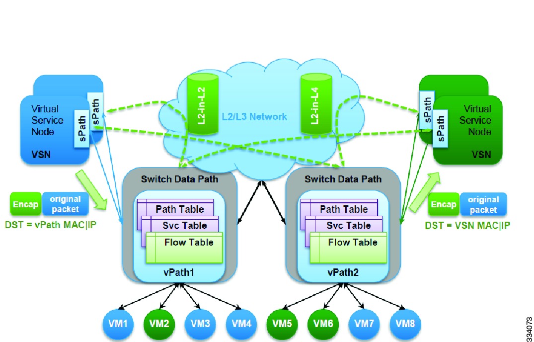
Cisco Virtual Service Data Path (vPath) is the service intelligence embedded in the Cisco Nexus 1000V Series switch.
vPath provides the forwarding plane abstraction and programmability required to implement the Layer 2 to Layer 7 network services such as segmentation firewalls, edge firewalls, load balancers, WAN optimization, and others. It is embedded in the Cisco Nexus 1000V Series switch Virtual Ethernet Module (VEM). It intercepts the traffic whether external to the virtual machine or traffic from virtual machine to virtual machine and then redirects the traffic to the appropriate virtual service node (VSN) such as Cisco Virtual Security Gateway (VSG), Cisco ASA 1000V, Cisco Virtual Wide Area Application Services (vWAAS) for processing. vPath uses overlay tunnels to steer the traffic to the virtual service node and the virtual service node can be either Layer 2 or Layer 3 adjacent.
The Cisco network virtual service (vService) is supported by the Cisco Nexus 1000V using the vPath. It provides trusted multitenant access and supports the VM mobility across physical servers for workload balancing, availability, or scale.
The basic functions of vPath includes traffic redirection to a virtual service node (VSN) and service chaining. Apart from the basic functions, vPath also includes advanced functions such as traffic off load, accleration and others.
vPath steers traffic, whether external to the virtual machine or from a virtual machine to a virtual machine, to the virtual service node. Initial packet processing occurs in the VSN for policy evaluation and enforcement. Once the policy decision is made, the virtual service node may off-load the policy enforcement of remaining packets to vPath.

Image result for virtual services data path

Cisco Virtual Security Gateway
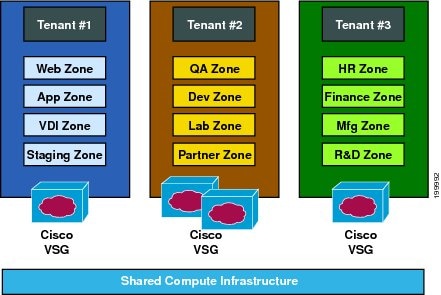
The Cisco Virtual Security Gateway (VSG) is a virtual firewall appliance that provides trusted access to virtual data center and cloud environments. The Cisco VSG enables a broad set of multitenant workloads that have varied security profiles to share a common compute infrastructure in a virtual data center private cloud or in a public cloud. By associating one or more virtual machines (VMs) into distinct trust zones, the Cisco VSG ensures that access to trust zones is controlled and monitored through established security policies.
Integrated with the Cisco Nexus 1000V Series switch and running on the Cisco NX-OS operating system, the Cisco VSG provides the following benefits :
  • Trusted Multitenant Access—Granular, zone-based control and monitoring with context-aware security policies applied in a multitenant (scale-out) environment to strengthen regulatory compliance and simplify audits. Security policies are organized into security profile templates to simplify their management and deployment across many Cisco VSGs.
  • Dynamic operation—On-demand provisioning of security templates and trust zones during VM instantiation and mobility-transparent enforcement and monitoring as live migration of VMs occur across different physical servers.
  • Nondisruptive administration—Administrative segregation across security and server teams while enhancing collaboration, eliminating administrative errors, and simplifying audits.

The Cisco VSG provides the following advantages:
  • Enhances compliance with industry regulations
  • Simplifies audit processes in virtualized environments
  • Reduces cost by securely deploying a broad set of virtualized workloads across multiple tenants on a shared compute infrastructure, whether in virtual data centers or private/public cloud computing environments

Cisco Adaptive Security Virtual Appliance

The Adaptive Security Virtual Appliance is a virtualized network security solution based on the market-leading Cisco ASA 5500-X Series firewalls. It supports both traditional and next-generation software-defined network (SDN) and Cisco Application Centric Infrastructure (ACI) environments to provide policy enforcement and threat inspection across heterogeneous multi-site environments.

Features and capabilities

1. Purpose Built for Data Center Security

The Adaptive Security Virtual Appliance brings full ASA firewall and VPN capabilities to virtualized environments to help safeguard traffic and multitenant architectures. Optimized for data center deployments, it’s designed to work in multiple hypervisor environments, reduce administrative overhead, and increase operational efficiency.
Virtual-switch independent, it may be deployed in Cisco, hybrid, and non-Cisco based data centers. VMware, KVM, Hyper-V, Amazon Web Services, and other cloud platforms offer flexibility and choice.
Predetermined configurations accelerate and simplify security service provisioning to match the speed of application deployment. These configurations provide the appliance with critical security functions that dynamically scale to protect assets as business demands change.
2. Fully Integrated ACI Security
The appliance has been fully and transparently integrated into the fabric of the next-generation Application Centric Infrastructure data center architecture. For those deployments, the Cisco Application Policy Infrastructure Controller provides a single point of control for both network and security management. It can provision the appliance’s security as a service, manage policy, and monitor the entire network and security environment for a unified view. This approach removes the limitations of traditional network-oriented security solutions, allowing for significantly streamlined provisioning.
In the ACI topology-independent environment, ASAv services are managed as a pool of security resources. These resources can be selected and attached to specific applications or transactions to provide dynamic, scalable, policy-based security.
3. Management Options
The virtual appliance, along with the physical ASA 5500-X Next Generation Firewalls can be managed by security administrators as a pool of resources that scale on demand. It provides programmable automation for deployment and management and uses a common policy-based operational model across physical and virtual environments, reducing cost and complexity.
Management options include the following.
Representational State Transfer (REST) application programming interface (API): This API simplifies device management; integrating the virtual appliance with custom policy orchestration systems used in SDN environments.
Cisco Security Manager: You can use this solution for comprehensive multi-device deployment and management of both the virtual appliance and the physical ASA 5500-X appliances. You gain a consolidated view of the entire firewall and VPN policy across the network.
Cisco Adaptive Security Device Manager: This no-cost GUI-based single-device management option can be used for configuring, monitoring, and troubleshooting the virtual and physical appliances.
Command-line interface: A flexible command-based management interface uses scripting for quick provisioning and automation of the appliances.

Cisco Cloud Service Router 1000v
The Cisco CSR 1000v Cloud Services Router provides a cloud-based virtual router deployed on a virtual machine (VM) instance on x86 server hardware. It supports a subset of Cisco IOS XE software features and technologies, providing Cisco IOS XE security and switching features on a virtualization platform.
When the Cisco CSR 1000v is deployed on a VM, the Cisco IOS XE software functions just as if it were deployed on a traditional Cisco hardware platform.

Features

The Cisco CSR 1000v includes a virtual Route Processor and a virtual Forwarding Processor (FP) as part of its architecture. It supports a subset of Cisco IOS XE software features and technologies.
The Cisco CSR 1000v can provide secure connectivity from an enterprise location, such as a branch office or data center, to the public or private cloud.
The Cisco CSR 1000v is deployed as a virtual machine on a hypervisor. Optionally, you can use a virtual switch (vSwitch), depending on your deployment. You can use selected Cisco equipment for some components. The supported components will depend on your software release.

Benefits of Virtualization Using the Cisco CSR 1000v Series Cloud Services Router

The Cisco CSR 1000v Series uses the benefits of virtualization in the cloud to provide the following:
  • Hardware independence
    Because the Cisco CSR 1000v runs on a virtual machine, it can be supported on any x86 hardware that the virtualization platform supports.
  • Sharing of resources
    The resources used by the Cisco CSR 1000v are managed by the hypervisor, and resources can be shared among VMs. The amount of hardware resources that the VM server allocates to a specific VM can be reallocated to another VM on the server.
  • Flexibility in deployment
    You can easily move a VM from one server to another. Thus, you can move the Cisco CSR 1000v from a server in one physical location to a server in another physical location without moving any hardware resources.
Citrix NetScaler 1000V

It is an application delivery controller solution, and part of the Cisco Cloud Network Services architecture. It gives applications critical performance enhancements, including offloading application servers, helping guarantee quality of service (QoS), and improving end-user experiences.

Features and capabilities 
deploy the Citrix NetScaler 1000V on demand, anywhere in the data center, using the Cisco Nexus 1100 Series Cloud Services Platform (CSP) with Hardware SSL offload or running as a virtual appliance on ESXi or KVM. When running on KVM, you can integrate it with OpenStack using the Cisco Prime Network Services Controller.
The simplicity and flexibility of the NetScaler 1000V make it cost-effective to fully optimize every web application and more effectively integrate networking services with application delivery.

Integrating the Citrix Netscaler 1000V with Cisco ACI

Cisco Application Centric Infrastructure (ACI) supplies the critical link between business-based requirements for applications and the infrastructure that supports them. The Citrix NetScaler 1000V connects infrastructure and applications. It makes their configuration available to the Cisco Application Policy Infrastructure Controller (APIC) through integration.
Citrix NetScaler 1000V and Cisco ACI help data center and cloud administrators to holistically control Layer 2 to Layer 7 network services in a unified manner. You do this through seamless insertion and automation of best-in-class NetScaler 1000V services into next-generation data centers built on Cisco's ACI architectures.
NetScaler 1000V uses the APIC to programmatically automate network provisioning and control on the basis of application requirements and policies for both data center and enterprise environments. Cisco ACI defines a policy-based service insertion mechanism for both physical and virtual NetScaler 1000V appliances.
Cisco Virtual Wide Area Application Services 
Cisco Virtual WAAS (vWAAS) is the first cloud-ready WAN optimization solution that accelerates applications delivered from private and virtual private cloud infrastructure, using policy-based on-demand orchestration.
Cisco vWAAS can be:
  • Virtualized on the industry-leading VMware ESX and ESXi hypervisor
  • Deployed on Cisco Unified Computing System x86 servers in an on-demand, elastic, and multitenant manner
  • Integrated with Cisco Nexus 1000V, which optimizes application delivery in a virtual machine environment through Cisco vPath architecture services.

Cisco vWAAS Benefits

Cisco vWAAS is designed for both enterprises and service providers to offer private and virtual private cloud-based application delivery service over the WAN. vWAAS provides:
  • On-demand orchestration of WAN optimization
  • Fault tolerance with virtual machine (VM) mobility awareness
  • Lower operating expenses for customers who are migrating their applications to the cloud

Cisco vWAAS Advantages

Cisco vWAAS is a WAN optimization service that gets deployed in an application-specific, virtualization-aware, and on-demand manner. This solution:
  • Uses policy-based configuration in the Cisco Nexus 1000V to associate with server VMs as they are instantiated or moved
  • Helps enable cloud providers to offer rapid creation of WAN optimization services in cloud-based environments
  • Supports transparent deployment at the network edge using WCCP providing deployment flexibility and feature consistency

vPath Service Chains

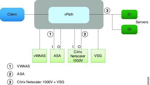
Service chaining allows multiple service nodes to be included in a service path so that the packets that belong to a particular flow can travel through all the virtual service nodes in the sevice chain. Each service node in a chain uses the security profile specified in the vservice command for that VSN.
A service path consists of an ordered list of services to be applied to a packet flow and it is used to define the service chain. When a packet reaches a virtual machine with vPath service chaining enabled, vPath intercepts the packet and redirects the packet to multiple VSNs in a specified order.
vPath thus acts as an orchestrator of the chain to deliver multiple services and VNMC enables the provisioning of service chains.


Related image

Cisco VACS Containers

A container is a set of virtual components such as routers, firewalls, and other network services that are systematically configured to deploy varying workloads. Cisco VACS enhances the Cisco UCS Director container abstraction, adds more controls and security features, and provides ready-to-deploy containers with built-in customization. Each Cisco Virtual Application Container Cisco VACS instance consists of the following components:
  • A Cisco Cloud Services Router (CSR) 1000V virtual router with multiple networks on which workloads are placed and a single uplink with a Layer 3 connection to the datacenter network.
  • A Cisco Virtual Services Gateway (VSG) zone-based firewall to control and monitor segmentation policies within the networks.
A Cisco prime Network Services Controller (PNSC) that defines and monitors the zone policies. A PNSC can span across multiple containers and the security policy configuration is done by PNSC.
Each container is provided switching by one Cisco Nexus 1000V switch. The Cisco Nexus 1000Vswitch instantiates the networks as port profiles. A single Cisco Nexus 1000V switch can provide switching for multiple containers.

Types of Cisco VACS Container Templates

Cisco VACS provides you with three different kinds of application container templates. Depending on the specific needs of your virtual application, you can choose one of the following templates:

1. Three Tier Internal Container template

The Cisco Virtual Application Services (Cisco VACS) three tier internal container template offers a preset collection of virtual resources that you can deploy in your datacenter. The internal template defines and enforces the overall policy in the web, application, and database tiers on a shared VLAN or VXLAN and achieves minimum required segregation and enables you to choose a private or public address on the gateway. This template enables you to have external connectivity only to the web tier and restricts the application and database tiers from exposing their services or from consuming the services exposed by other applications inside a firewall.
The three tier internal container template uses Enhanced Interior Gateway Routing Protocol (EIGRP) as the default routing protocol if you choose the Public Router IP type. However, you have an option to choose either the EIGRP protocol or set up Static Routing Protocol, and set up other static routes to forward upstream traffic to the container's internal network.
2. Three Tier External Container template
The Cisco VACS 3 Tier external container template retains all features of a 3 tier Internal template and also allows external access to application and database tiers in addition to the web tier .This template type allows you to expose the services of the container to external applications and consume the services exposed by other applications behind the firewall. As with the internal template type, the specific security profile requirements for the tiers are enabled by the zone ans security policies.
3. Custom Container template
The Cisco Virtual Application Container Services (Cisco VACS) Custom Container (or Advanced Container) template enables you to design a container that meets your specific requirements without any restrictions on the number of tiers, zones, network, and application types. The custom container type allows you to build a template that allows an n-tier application with each tier on a shared or dedicated VLAN or VXLAN segments.
The Cisco Virtual Application Container Services Cisco VACS guidelines and limitations are as follows:
  • Cisco VACS supports only a new installation of the Cisco Nexus 1000V and Cisco PNSC.
  • Cisco VACS supports Cisco UCS Director, Release 5.1 and the following versions of the related components:
    • Cisco Nexus 1000V, Release 5.2(1)SV3(1.1)
    • Cisco PNSC, Release 3.2.2.b
    • Cisco Virtual Services Gateway (VSG), Release 5.2(1)VSG2(1.2)
    • Cisco Cloud Services Router 1000V, Release 3.12
  • You can add or edit a container template, and then instantiate containers from the template.
  • Cisco VACS supports VMware ESX 5.0, 5.1, and 5.5 and VMware vCenter 5.1 and later versions. We recommend that you use vCenter version 5.5 because it is compatible with all versions of VMware ESXi.
  • The number of virtual machines that you can add to a container template is limited only by the hardware of your setup.
The Cisco Virtual Application Container (Cisco VACS) template has the following prerequisites:
  • Set up a VMware vCenter account on Cisco UCS Director.
  • Define the Network Policy. A network policy includes the VLAN pool policy, the VXLAN pool policy, Statis IP pool policy, and the IP Subnet pool policy.
  • Define the Computing Policy. Computing policies determine the computing resources used during provisioning that satisfy group or workload requirements.
  • Define the Storage Policy. A storage policy defines resources, such as the datastore scope, type of storage to use, minimum conditions for capacity, and latency. The storage policy also provides options to configure additional disk policies for multiple disks and to provide datastore choices for use during a service request creation.
  • Define the Systems Policy. A system policy defines the system-specific information, such as the template to use, time zone, and operating system-specific information.

Network Architectures for the Data Center: SDN and ACI

This chapter covers the following topics:  ■ Cloud Computing and Traditional Data Center Networks  ■ The Opposite of Software-Defined ...